คำตอบที่ 5
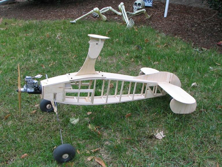
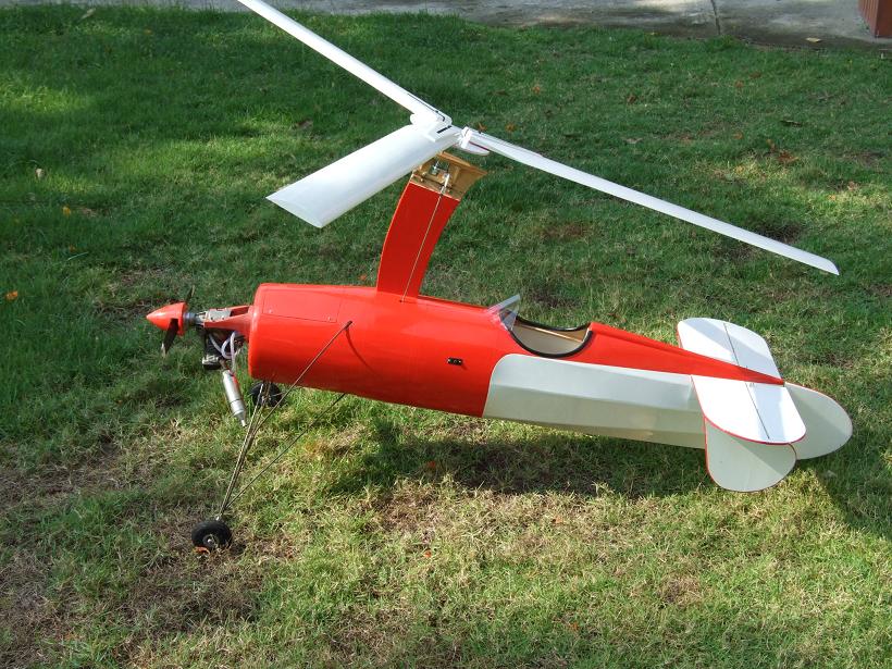
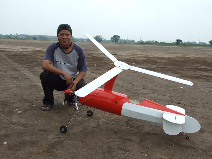
The average specs & parameters for a flyable
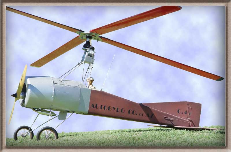
tractor powered ...... MODEL AUTOGYRO
This file will occasionally undergo a few revisions, I will attempt to mark those revisions as "new". Hopefully I will be able to eventually present a few important key specs in relative to the design of a "pusher" type model.
Except where specifically noted, this graphic applies only to R/C non-winged tractor style (engine in front) model Autogyros and also does not fully cover all the experiences of every Autogyro modeler.
An Autogyro.... is very different in many ways when compared to either an Airplane (fixed wing) or a Helicopter. An Autogyro is not a modification of the Helicopter.... The Helicopter is a modification of the Autogyro.
This information is posted here simply as an aid to those modelers interested in trying their hand at designing, building, and flying a model of their own... It can also be of great help in determining why a model is not performing as well as anticipated. Keep in mind that if you deviate from the average or norm in one area, it will potentially / adversely affect another parameter.
Simply put, the Autogyro depends on an initially high positive angle of attack of the rotor to initiate acceleration, and while the angle of attack remains positive (average of about 10 degrees) , throughout the flight, lift is still produced by down flow from the rotor blades. While it appears that the airflow is constantly "up" thru the rotor, technically this cannot produce lift. Since our simple Autogyro models have an unpowered rotor, and a fixed incidence pitch of the blades, we tilt the rotor to accomplish a climb, descent, or turn.... whereas the Helicopter depends on pulling the airflow "down" through the rotor, by varying the blade incidence, of a powered rotor.. and is able to change attitude by simply cycling the incidence of the blades. Our autogyros must have a lifting airfoil on the blades, whereas the helicopter blade airfoil is generally symmetrical.
To control the direction of our gyros we will tilt the rotor disk just as you would the wing / tail of an airplane. along with providing some sort of stabilizing tail fins... We can directly tilt the rotor via servos, use an elevator and rudder, or a combination of both. Without the full cyclic blade control of the blades of the helicopter, we also must provide a propelling engine to pull or push the Autogyro forward through the air. All these are basically what separates the gyro from the heli... in as simple terms as I can express.
It is not a simple matter to find the proper balance of angles and measurements for a model Autogyro. They are far more critical with this unique type craft than the average fixed wing model airplane. The angles and measurements mentioned here have been accumulated thru years of experience and experimentation, and are close approximates. They do not fully apply to models that utilize a small to medium sized wing (such as the Gyrace, or even the Whistler). Nor do they apply to a modified helicopter such as the Robbe Whopper, Kalt Robin, or the Micro-Mold Wallis models labeled as Autogyros. Those latter models are basically helicopter models without a powered rotor, and an engine installed to compensate for this change..
Keep in mind that a particular model may necessarily deviate from the above slightly, due to differences in design (tractor versus pusher), etc. Technically it seems far easier to begin with an all new model, versus trying to convert a model not originally designed as a gyro or even a tail controlled gyro not originally designed as a DC (Direct servo Control) gyro. Please read over the following explanations in regard to some of these differences.
--------------------------------------------------------------------------------
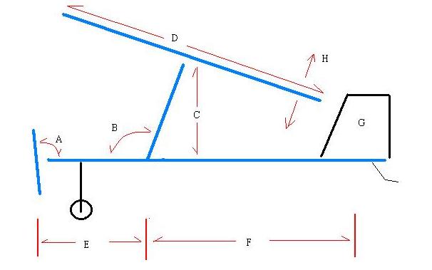
A: Engine Downthrust... 5 degrees (3 to 8 degrees)
Engine downthrust is necessary for a model Autogyro to aid in overcoming the drag of the rotor system, which is located high ( vertically) above the horizontal centerline and Center of Gravity of the craft.. It would be nice to have the Thrustline project thru the Center of Gravity (which, by the way, is virtually necessary with the "pusher" models), (CG) however this is impractical for most of these models, so we use just enough to assist in maintaining a level flight attitude. A Downthrust of 10 to 15 degrees is not unheard of, however this high amount is indicative of a rotor being placed perhaps too high, creating excessive drag. Placing the rotor as low as practical should reduce the DT to the 5 to 8 degree average many of us find works very well. If you have a model that seems to be flying tail low all the time, it may have insufficient downthrust, or perhaps it also needs a "lifting airfoil" on the stabilizer, or the incidence of the stab needs to be shimmed slightly positive (giving it a slight lift). Consider also the relative strength of your motor. If you know your motor is in the small / low power range, it may require slightly more DT as an aid in countering rotor drag.
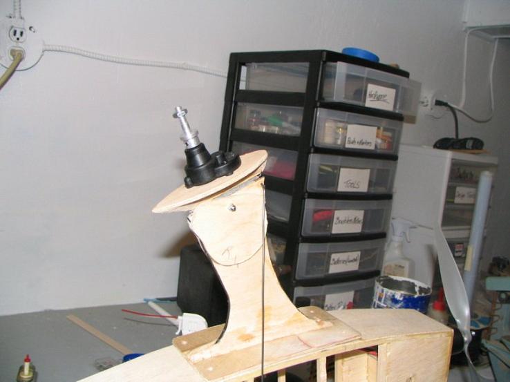
B: Mast angle or Aft Rotor Tilt.(aft of a true vertical line) .. 10 degrees (6 to 14 degrees)
This is the amount (in degrees) the rotor shaft (thus the incidence of the entire rotor disk / plane of the rotor) is tilted aft for an initial (zero pitch trim) position. Much seems to depend on the type/location of the stabilizer system installed, as well as the amount of downthrust, and the CG location. As an example, With a lifting stab`, the angle will probably be 10 degrees or more. With a relatively flat stab` the angle will decrease. If you find your model requires more aft tilt than this in the neutral trim position, you may have too much downthrust or the model may be nose heavy, with a larger than normal "hang angle". A correction in this situation could mean a slight aft shifting of the CG, and / or a decrease in downthrust.
C: Rotor Disk Height... roughly equal to "E" , but no more than "E", plus perhaps 25%.
This can be a highly variable measurement. One finding is that the higher the rotor (vertically) the more stable the model, however the more difficult to accomplish a decent coordinated turn (it may possibly "resist" a turn). The lower the rotor height, the more maneuverable a model may be, but less overall stable. A model utilizing a very high (vertically) rotor position will generally require coordinated rudder assistance to complete a turn. With totally direct control (fins without rudder or elevator) models, the rotor height is more critical to accomplish coordinated flight, therefore are more difficult to design and fly. However, a properly designed DC model is more controllable throughout its speed range, and can be controlled down to zero forward airspeed, versus strictly a rudder/elevator and no tilting rotor. Some full sized flyers may not find this true of their craft, however it is something we have found to be true with these models.
D: Rotor Disk Diameter... sufficient to equate to a disk load of less than 5 ounces per sq. foot.
The lower the disk load, obviously the better chance the model has to fly. Models with loads over 6.0 are relatively heavy, and will experience problems with hovering in anything less than a strong breeze. They will also require a longer ground T/O distance and/or be more difficult to hand launch. Many of the finer flying models have disk loads in the area of 2 to 3... You should probably review the following graphic charts on this subject: Model Autogyro Flight Prediction Chart and Model Autogyro Calculations. You may think "why not just increase the rotor size to obtain the lower (better) disk loading?" Well, that's not the simple solution. By simply increasing the size of the rotor you also increase the rotor drag, and this is something you must consider before making such a change.
Rotor Disk Solidity...3 or 4 blades recommended (number of rotor blades..)
The actual number of rotor blades is not critical for model performance. We note that rotor RPM may decrease some as you add blades, thus simply the adding of blades does not significantly alter the rotor performance. A single, counter balanced blade, would possibly work, however it`s use is not as practical as two or more. Two rotor blades work fair, but experience with models tells us they are not as efficient or as easy to pre-spin as three or four.. Three blades perform exceptionally well, and many modelers report they seem to add a bit more stability and steadiness to a model. Four blades work very well, and will improve rotor efficiency slightly, if you want to go to the effort to built more than three blades. If your model is an attempt at scaling a full sized machine using four or more blades, use the correct number, however do not expect much (if any) increase in efficiency. Suggestion: It is a good idea when you make blades, to make an extra identical one for the set...... Sooner or later you will probably need to replace a blade.
Rotor Blade Aspect Ratio...10:1 is a good place to begin (length versus chord-width)
An acceptable range for blades that always seem to work for these models is sometimes can be anywhere from 8:1 to 12:1. With the ratio of 10:1 being a good place to begin with. This fact was verified in the spring 2000 wind tunnel tests. Short / wide ones will work, as well as long narrow ones, however the most consistently efficient ones seem to be within the range mentioned above. Thickness at the maximum lift point of the chord should also be watched. Blades with a thickness of over 16% of the chord tend to have a more blunt (higher radius) leading edge, and thus are a bit too thick. They also tend to be more difficult to pre-spin. Measuring quite a few of the blades that seem to be more efficient for these models, the range is 13% to 16%, with the majority closer to the 13% area. The leading edge should not be highly round or blunt... A fairly narrow leading edge radius is desirable, along with a thin trailing edge.. We accomplish this by using the Clark W, K, or Y airfoil, with a flattened out bottom, into what we generally refer to as a "flat bottomed Clark-Y" airfoil. Full sized "rotorcraft" (gyroplanes) frequently have a slightly "reflexed" trailing edge to their blades (Clark - YS), which aids in preventing "tuck under".of the leading edge... This reflex is usually in the form of a slightly up-turned trailing edge, and has been found to work well on models, however is difficult to make. If you have the capability of building slightly more complex airfoiled blades, seriously consider the SG6042 for your airfoils... This airfoil scored exceptional in the spring 2000 wind tunnel tests.
E: Nose (prop) to Rotor Mast.. roughly equal to "C", keep short, just sufficient to balance the model just forward of the rotor shaft.
For stability the rotor normally is placed higher than the length of the nose. If you want to employ direct servo rotor control (DC) to control the model, extending the nose too far may make it difficult to impossible for the model to initiate a turn without the additional use of a rudder. Also remember for each added bit of length or weight to the nose section, you may have to add at least 1/2 that weight to the tail section to maintain balance. The point is.... keep the nose short as practical.
Center of Gravity....
The model needs to balance just forward of the rotor shaft, and will necessarily be above the fuselage due to the volume, weight, and drag of the rotor system. This latter item is one major difference to the average model airplane, and must be kept in mind. Due to the configuration of an Autogyro this may place the CG in a position where you cannot "grasp" the model at this point. To check for balance/CG location, hold the model by the rotor shaft and note the nose down attitude of the model in reference to a horizontal line through the center of the fuselage to the tail. This is what we call "hang angle" and will vary from model to model, however the average is around 5 to 10 degrees (nose down). Just as with disk loading, the higher the hang angle, the heavier the model may fly. The less, the lighter it will fly, but may be less stable. Just remember... if the model is balanced directly at the center of the rotor (shaft) it will be extremely sensitive in both pitch and roll, therefore it is much easier to control with a slightly forward CG... A tractor model with very little or no hang angle may not assume a nose down glide with engine failure, and thus will be virtually uncontrollable. A model under these conditions will simply drift with the breeze and hopefully complete a parachute type descent.
An Autogyro aircraft behaves just like a fixed wing model aircraft in regard to CG location.. . As the CG is moved aft, the model will become increasingly control sensitive and perhaps uncontrollable. However if you elect to move the CG forward too much (increasing the hang angle ) , the model will begin to fly like it is overweight. If your model seems to require an excessive amount of down hang angle, then you are perhaps correcting for an excessive rotor height (spec "C" above) or some other sort of stability problem in your system that needs attention? Note that you can fairly well locate the exact Center of Gravity by noting the vertical line through the model while holding the model by the propellor shaft, and noting where the hang line passes through this line...
F: Rotor to Tail distance.. normally double the distance "E" ..
Extending the tail unnecessarily may create a similar problem as stated above in regard to extending the nose. Once you establish the size of the rotor desired, place the tail fin just aft of the max radius of the rotor (by perhaps 1/2 to 1").. This applies to models where the tail is aft of the rotor. If your model has an aft fuselage that can flex upon touchdown on landing, additional clearance may be needed. Normally under controlled conditions, and with properly tip weighted rotor blades, the rotor will not flap down on impact, however with a Fiber tube fuselage it is very possible for the fuse / tail to flex upward and strike the rotor.
G: Vertical Fin Area... approximately 2.0 to 3.5 % of the Rotor Disk Area. (and approximately 45 to 55 % of the horizontal stabilizer area)
This will vary greatly depending on the particular design, with this figure applying to the model with the tail aft of the rotor blade tips. The tail feathers need to be kept close (but allow at least ? to 1") blade tip clearance. Extending the tail well aft of the model may increase its stability, however decrease its ability to complete a coordinated turn without the need for lots of rudder assistance. Enlarging the rotor and extending it aft /over the tail changes several variables, which will not be covered until a later revision of this page.
Horizontal Stabilizer Area... approximately 5 to 8 % of Rotor Disk Area. If the rotor is directly servo controlled, and elevator + rudder control is not used, the tail can be slightly smaller in size.
A few DC models have been known to fly without a horizontal stabilizer, and a smaller vertical fin... however at least some horizontal stabilzer is desirable, and a good average sized vertical fin is virtually always necessary.... A few simple tests were completed with the Horizontal Stabilizer moved forward 1 / 2 the distance from the rotor mast and highly erratic model behavior was noted. However moving the Vertical Fin forward had very little effect, with the model remaining stable.
H: Rotor Pitch control limits ... + / - 8 degrees
Rotor Lateral Tilt control limits... + / - 7 degrees.
This applies to rotors that have Direct Servo Control (DC).. Models seem to be far more sensitive in Roll than in Pitch.. A new model may be oversensitive in roll if you install more tilting than mentioned here. However initially you may want to install slightly more than the 8 degrees of pitch tilt to provide a cushion of control. NOTE: it is not unusual for some models to resist a roll/turn to the left, and may require some left trim. Some new models have been found to be unable to turn left on the first flight, so it may be advisable to install an extra 2 to 3 degrees of left roll tilt throw on the initial flight tests, with a possible subsequent requirement of for a pre-set left tilt trim a several degrees for all flights..... This may mean a slight problem involving Dissymmetry of Lift (unbalanced lift towards one side) and while it is difficult to explain, it is almost always in the direction of the retreating blade. Note: most of us employ the counter - rotating (as viewed from the top) rotor, for several reasons, and in general we are always speaking of a CCW rotor.
Note: You can possibly detect this problem prior to the initial flights by conducting a hand-held-nose-high rotor test with the nose pointed into a good breeze... Allow the rotor to fully accelerate and note any tendency for the model to tilt to either side.
If it does, consider pre-trimming a couple degrees opposite the direction of roll. In otherwords, if it rolls to the left, trim a degree or two to the right. As mentioned before, it seems to always be in the direction of the retreating blade.
NOTE: I have noted an interesting situation regarding the above in reference to electric powered gyros. If you replace your electric motor with one of significantly more power, the model then will often roll to the left on initial flights. The larger propellor on the electrics produces a much stronger torque effect on these small models.
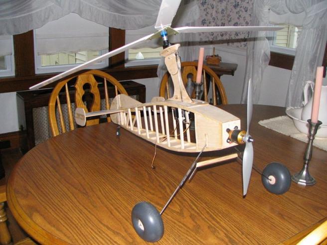
Model Weight: This is critical. Use the lightest building materials available, yet maintaining reasonable strength. Light Balsa, light Plywood, Carbon Fiber, etc. Use the smallest servos that will serve the purpose, such as sub micro and micro for throttles, strong sub-micro (20 - 25 ounce torque or higher), mini, or lightweight others for rotor controls under 1 meter ( 39" ). Small, compact battery packs, receivers, wheels, etc., are best..... anything to keep the gross weight down. You may be surprised to know that servo damage usually only occurs on the ground, not in flight. Tipping the model over on landing, tripping the blades can damage servos.... Never use more than 1 (one) hard bolt to mount the blades unless absolutely necessary for a very large model. A common blade mounting bolt being used is a 4x40... however for the smaller models (1 meter rotor or less) a 2-56 has been more than adequate (zero known failures to date) and a gram saved is important! In addition to a single bolt, use balsa shear pins for the small, and a nylon bolt is good for the larger models. This is to aid in keeping the blade straight during initial spin-up. If not, you will need to torque down the single bolt. I prefer the addition of a balsa pin rather than the single bolt simply because the torque of the single bolt requires a heavier bolt mounting and it`s frustrating to keep the blades aligned for pre-spin with a single bolt. For rotors over 4 feet (1.2 meters) , a nylon shear bolt works well, rather than the balsa pin. See this performance Chart...
Engine power: It is not necessary nor always advantageous to overpower a model Autogyro. The generally acceptable requirement a few years ago was for the thrust to equal at least ? of the weight of the model. If the model weighed 3#, then you needed a bare minimum of 1 ? pounds of thrust available. This now appears now to be an underestimate... Recent practical experience has demonstrated that the ? weight in thrust is marginal, especially when flying well above sea level. I`d suggest about 75% or more of the weight in thrust . In other words, if the model weighs two pounds, then you should use at least 1 ? pounds of thrust. A 1 to 1 ratio may not be necessary, and may be unwise unless the additional engine weight does not create an excessive disk loading. Using a large powerful (heavy) engine can also create an "overpower" situation at times. In regard to electric models, it is very difficult (with the weight of the current batteries being considered) to obtain sufficient power. Electric models must be built as light as possible.. For our reference purposes, a "strong" electric Speed 400 motor is about equal to .050 in glow motor (IC) power. Refer / to this chart...
To fully understand.. all the information presented here, you need to read over the many technical articles posted on this web site. Propellor size and use, as an example is different from a average / normal model airplane. We must necessarily go for power (larger diameter) and low speed (low pitch). The recent (1989-99) research / experimentation with the Electric versions, the almost necessary larger (than glow size) propellors has dramatically demonstrated that the torque effect of the larger prop will tend to turn these (smaller) models with throttle changes....
Remember: Except where specifically noted, this graphic applies only to tractor style, (engine in front) R/C models that do not employ an additional small fixed wing... and also does not fully cover all the experiences of every Autogyro modeler.
Jim Baxter, revised 22 Dec 2003
To the Technical Menu


 bullseye